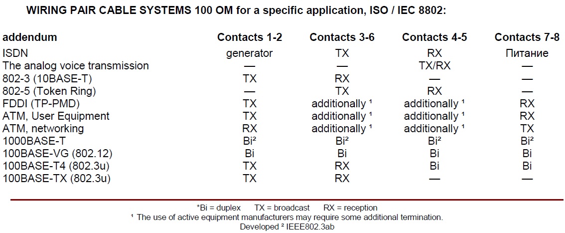
Довідник по модульним з’єднувачам.
Types of modular connectors:
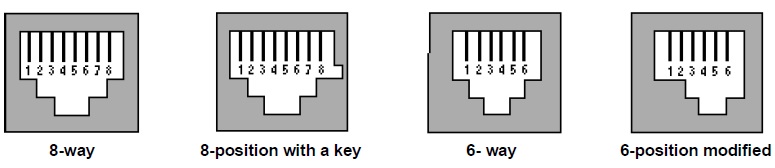
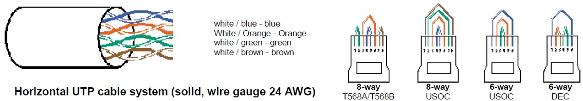
There are 4 basic types of modular connectors. 8-position modular jacks are usually incorrectly referred to as «RJ45», and 6-position — «RJ11». The use of these terms can lead to confusion, since the RJ designations usually refer to very specific configurations of wearing the common name «Universal Service Classification Codes» (Universal Service Ordering Codes, USOC). Designation «RJ» stands for «registered jack» (Registered Jack). Each of these basic types of connectors may have a wiring diagram and related to different configurations of RJ. For example, the 6-position jack can be connected as a RJ11C (1-pair), RJ14C (2 doubles), or RJ25C (3 doubles). 8-position jack can be connected as a RJ61C (4-pair) and RJ48C. 8-way connector with the key can be connected as RJ45S, RJ46S and RJ47S. The fourth type of modular connector — a modified version of the 6-position jack (modified modular jack or MMJ — Modified Modular Jack). It was developed by Digital Equipment Corporation ® (DEC) in a pair of modified modular plug (MMP — Modified Modular Plug) to exclude the possibility of connecting equipment for transmitting speech data to DEC lines and vice versa.
The usual configuration of outlets:
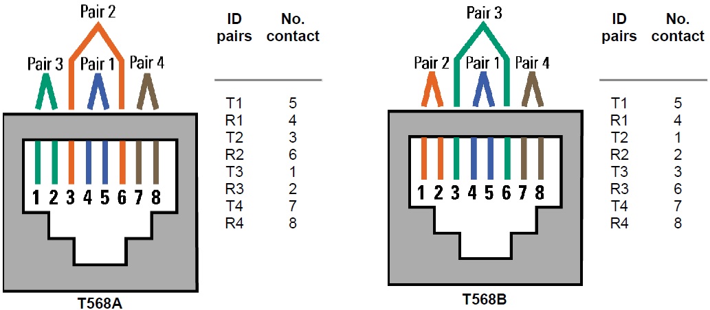
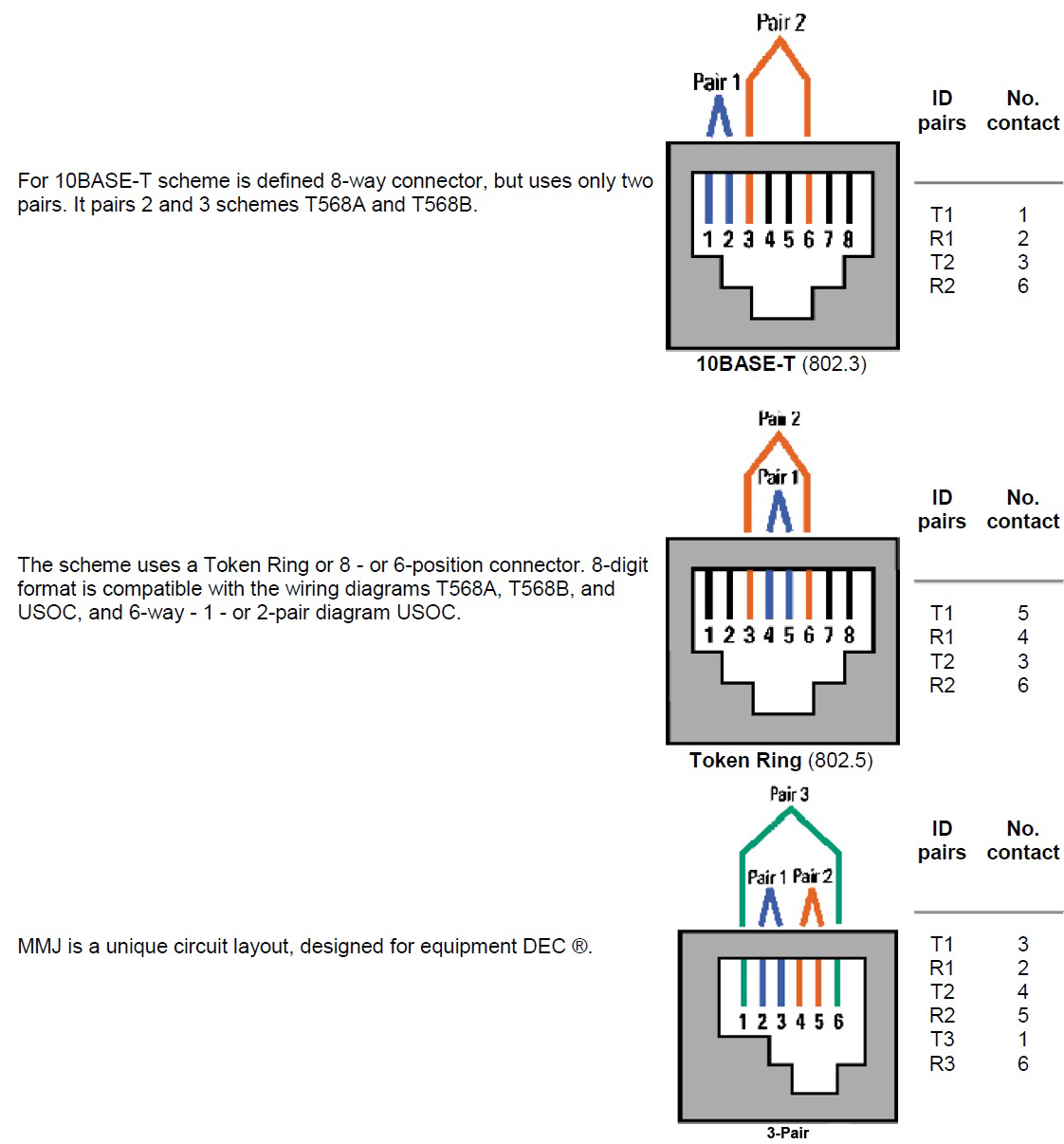
Adopted two wiring schemes. They are almost identical except that the pair 2 and 3 are reversed. T568A — preferred circuit as it is compatible with a 1 — or 2-pair systems USOC. For technology Integrated Services Digital Network (ISDN) and high data applications can use any of the circuits. Categories transmission characteristics of 3, 4, 5, 5e, and 6 are defined only for these types of grouping pairs.
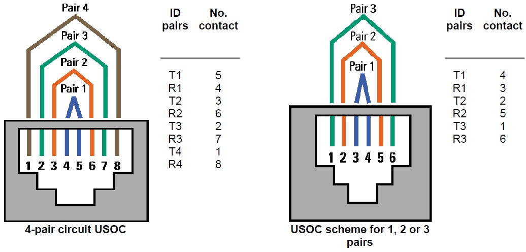
USOC scheme applicable to the 1 -, 2 -, 3 — or 4-pair systems. Pair 1 activates the central conductors 2 uses a pair of these two contact pins, etc. The main advantage of this scheme is that the 6-position plug is configured to 1, 2 or 3 pairs can be introduced into the 8-position and wherein the connector supports continuous steam. However, we consider it necessary to warn that pins 1 and 8 on the connector may be damaged by such practices. The disadvantage of the scheme is the poor transmission characteristics, which is associated with this type of sequence pairs. None of these schemes are not consistent with the standards of cable systems.
Configuration PAR Modular Plugs
It is important that the configuration in pairs of the modular plug is compatible with the configuration of the modular jack pairs, as well as horizontal and circuit wiring trunking systems. Otherwise, the transmitted data signals may affect power levels incompatible. Modular cords with wiring diagram corresponding to the color scheme on both ends of the T568A, T568B is compatible with systems and vice versa.
Direct or reverse run LAYOUT?
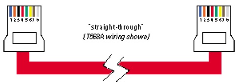
Modular cords are used for two main applications. In one of the cables used to connect modular patch panels. When used in this modular cords should always be collected by the «direct» scheme (pin 1 to pin 1, pin 2 to pin 2, pin 3 to pin 3, etc.). In the second main application modular cables are used to connect the equipment working mecta (PC, phone, fax, etc.) with a modular jack. Such modular cords can be connected or «direct» or «reverse» pattern (pin 1 to pin 6, pin 2 to pin 5, pin 3 to pin 4, etc.), depending on the specifications of the manufacturer. Such «Reversible» scheme is commonly used for speech transmission systems. Below are instructions for determining the type you are using modular cord.
HOW TO DETERMINE THE TYPE OF MODULAR CORD:
Align the fork side by side so that they are rotated to contact you compare numbers of conductors and left to right. If the colors are in the same order on both forks, the cord has a «line» wiring. If the colors on the second fork go in reverse order (right to left), the cord has a «reversnuju» wiring diagram.
Terminate a connector UTP:
• It is necessary to maintain twist pairs as close as possible to the point of termination.
• The quantity of steam does not exceed 25 mm (1 inch) to the lines of 4 and 13 mm (0.5 in.) for the lines of Category 5 and 5e. Follow the manufacturer’s instructions when using products category 3, and if not, the value of the development shall not exceed 75 mm.
• Switching equipment should be installed so that the installation of the cable system was well organized, with cable management and in accordance with the manufacturer’s instructions.
• Remove the cable jacket just as much as it is necessary to terminate the individual pairs.