Elections are held on the heating
Elections are held on the heating
SCOPE
1.3.1. This chapter of the Regulations applies to choose sections of electrical conductors (non-insulated and insulated wires, cables and tires) of the heating, the current density and economic conditions on the crown. If the conductor cross-section defined by these conditions, there is less cross-section required for other conditions (thermal and electrodynamic resistance to fault currents, losses and voltage deviations, mechanical strength, overload protection), it should be made the largest cross section required by these conditions.
SECTION OF THE CONDUCTOR OF THE HEATING
1.3.2. Conductors for any purpose must meet the requirements for the maximum allowable heat taking into account not only normal, but also post-emergency regimes and regimes in the period of repair and possible irregularities in the distribution of currents between the lines, sections of buses, etc. When checking for heat taken a half-hour maximum current maximum of half of the middle part of the current network element.
1.3.3. When intermittent and temporary service power consumers (with a total cycle time of 10 minutes duration and working period not exceeding 4 min) as the rated current for checking cross-section of conductors on the heating current should be given to long-term regime. In this case:
1) for copper conductors up to 6 mm, and for aluminum conductors up to 10 mm is accepted as current for systems with continuous operation;
2) for copper conductors larger than 6 mm, and aluminum conductors for more than 10 mm is determined by multiplying the current allowable continuous current by a factor of 0,875 / √ (Tp.v.), where Tp.v. — Expressed in terms of relative duration of the working time (duty cycle relative to a cycle duration).
1.3.4. For intermittent operation with a duration of no more than 4 minutes and intermittently between power sufficient for cooling the wire to ambient temperature, the greatest permissible currents should be determined by rules re — short mode (see 1.3.3). When the operating time of more than 4 minutes, and during breaks between the insertion of insufficient duration highest allowable currents should be determined for systems with continuous operation.
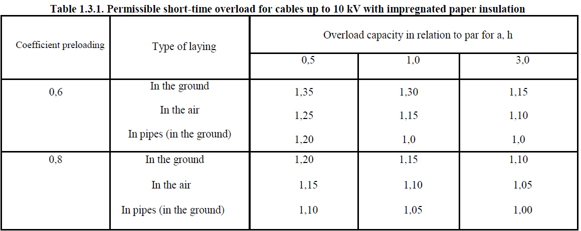
1.3.5. For cables up to 10 kV with impregnated paper insulation, less than the nominal load-bearing, short-time overload can be tolerated, given in Table. 1.3.1.
1.3.6. For the liquidation of failure mode for cables with polyethylene insulation overload capability up to 10%, and for cables with PVC insulation up to 15% of rated load at the time of the maxima of no more than 6 hours a day for 5 days., If the load in the remaining periods of these day did not exceed the rated capacity.
For the liquidation of failure mode for cables up to 10 kV paper insulated allowed overload for 5 days. within the limits specified in Table. 1.3.2.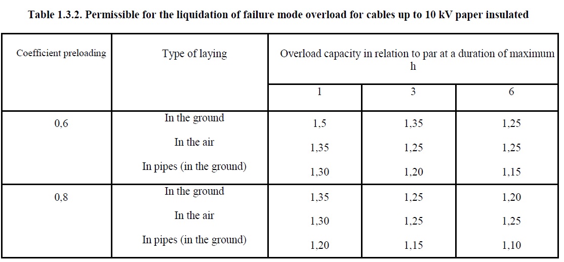
For cable lines in service for more than 15 years, overloading must be reduced by 10%.
Overloading cable lines 20-35 kV are not allowed.
1.3.7. Requirements for normal loads and disaster overload are the cables and set them on the connection and terminals and terminations.
1.3.8. Neutral conductor in the three-phase four-wire system must have a conductivity of at least 50% of the phase conductor, where necessary, it should be increased to 100% of the phase conductor.
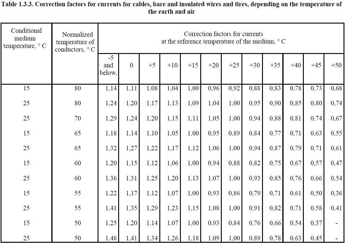
1.3.9. In determining the allowable currents for long cables, bare and insulated wires and tires, as well as for rigid and flexible conductors laid in an environment where the temperature differs from that given in 1.3.12-1.3.15 and 1.3.22, factors should be applied, are listed in Table. 1.3.3.
ALLOWED CONTINUOUS CURRENTS FOR WIRES, CORDS AND CABLES WITH RUBBER OR PLASTIC INSULATION
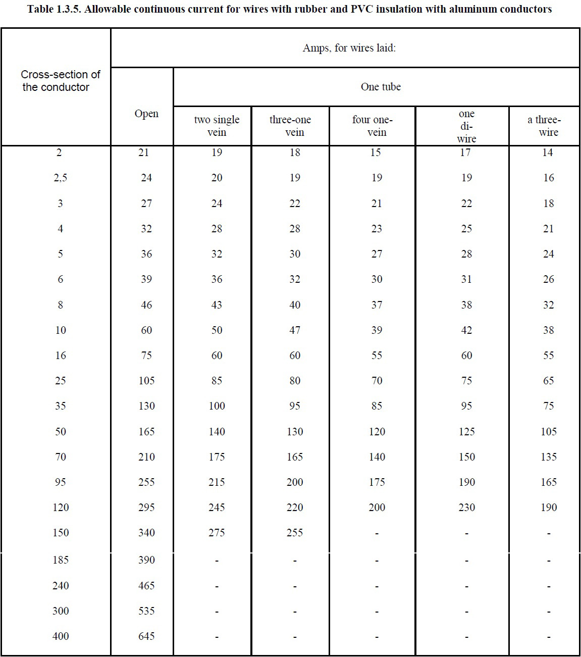
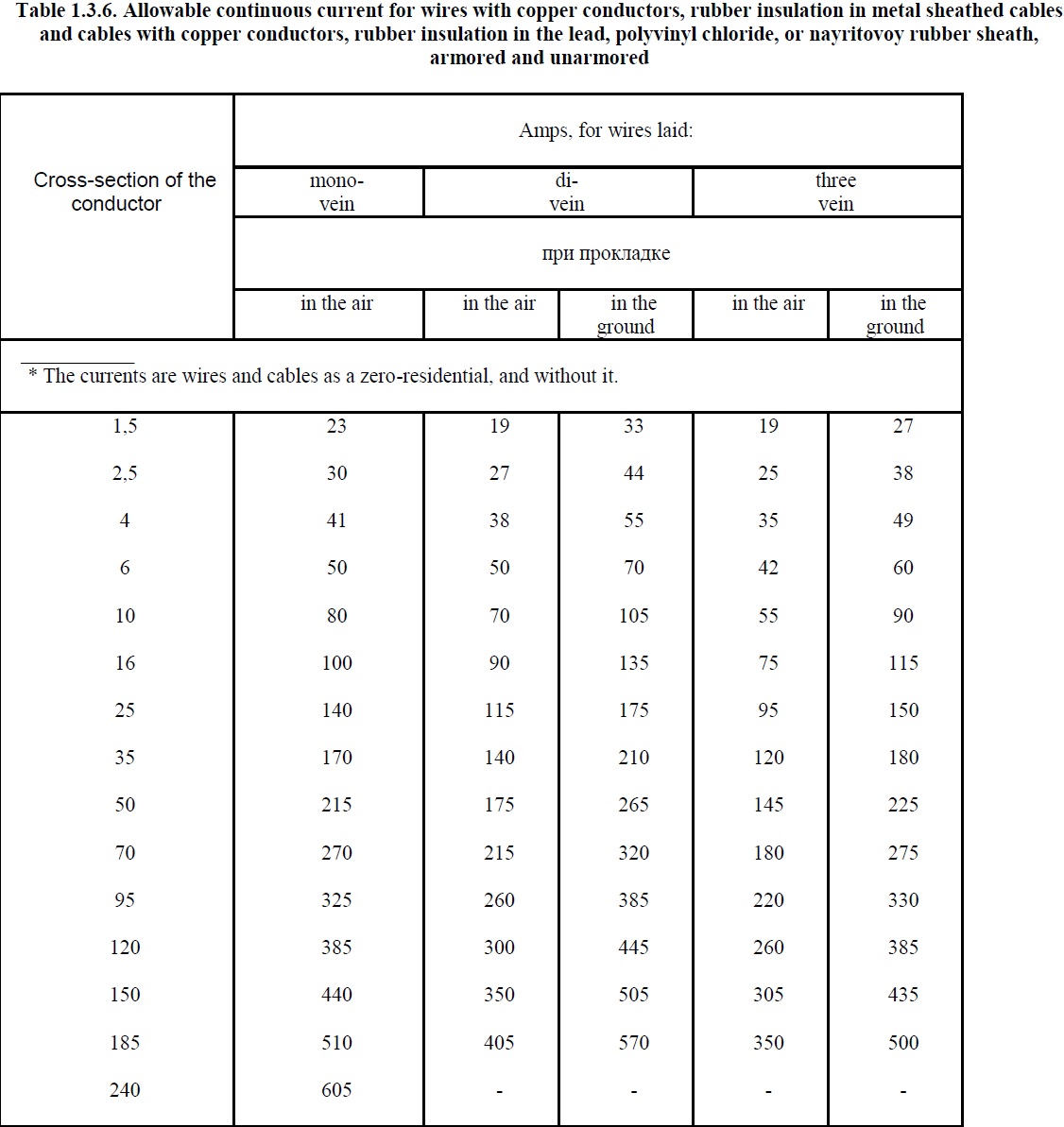
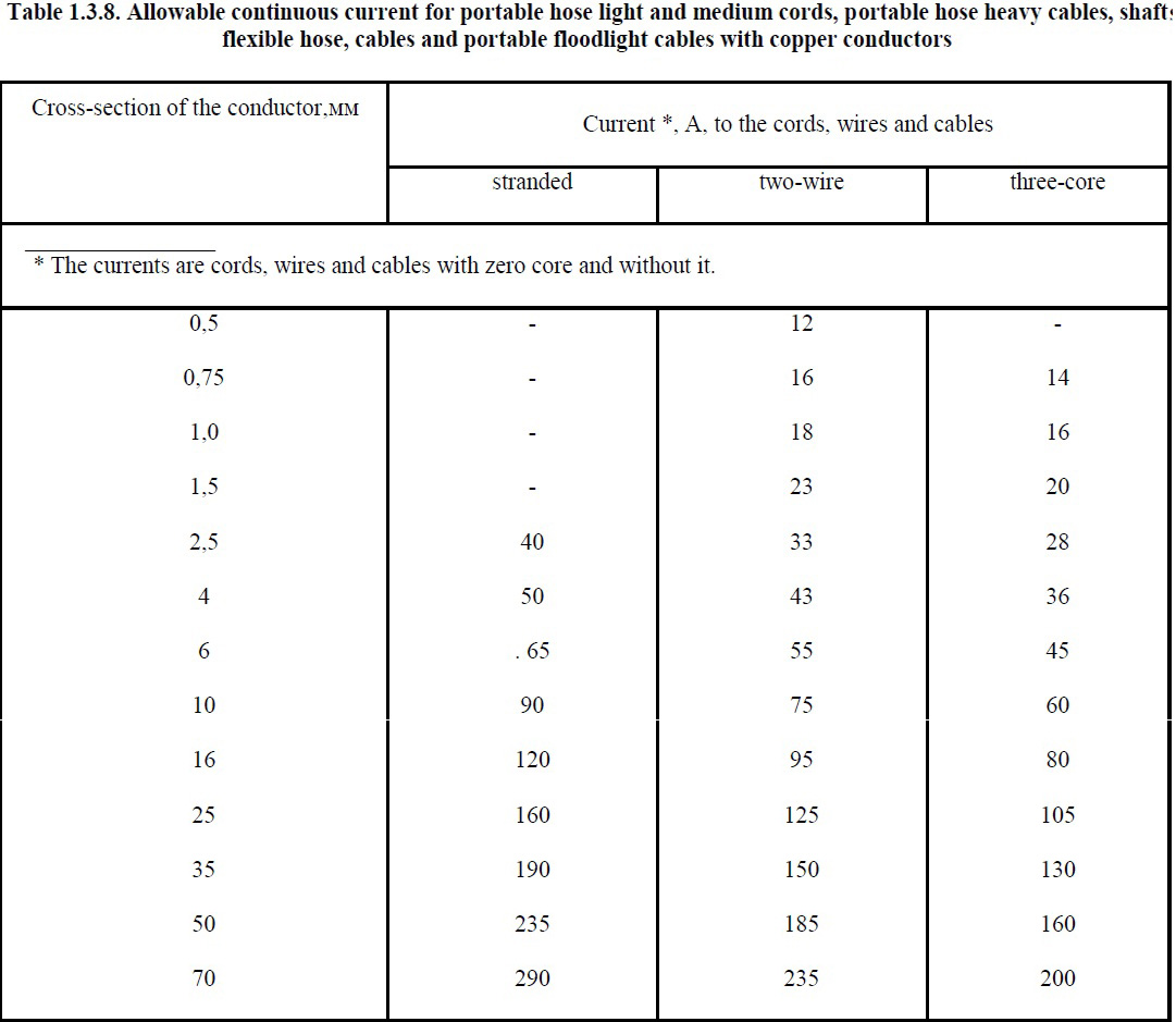
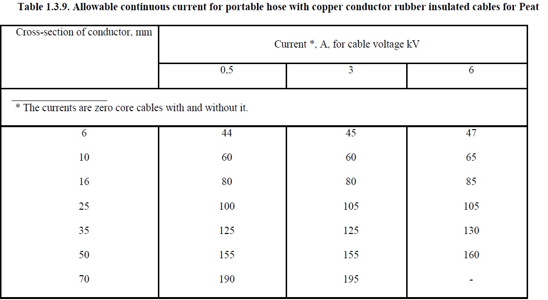
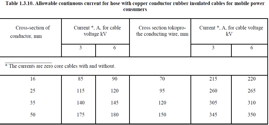
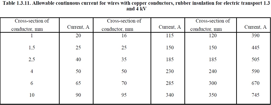
1.3.10. Allowed continuous current for wires with a rubber or PVC insulation, cords, rubber insulated cables with rubber or plastic insulation in the lead, PVC and rubber membranes are shown in Table. 1.3.4-1.3.11. They are taken for temperature: +65 lived, the air and the ground 25 + 15 ° C.
In determining the number of wires, put in a pipe (or lived stranded conductor), the neutral conductor three-phase four-wire system, with the ground and the protective conductor shall not be considered.
The data contained in the table. 1.3.4 and 1.3.5 should be applied regardless of the number of tubes and their place of installation (in the air, floors, foundations).
Allowed continuous current for wires and cables installed in ducts and trays in bundles must be taken: for wires — from Table. 1.3.4 and 1.3.5 for wires laid in tunnels, cable — according to Table. 1.3.6-1.3.8 for cables laid in air. When the number of simultaneously loaded with more than four wires laid in pipes, ducts and trays in bundles, the currents for conductors shall be taken from Table. 1.3.4 and 1.3.5 for wires laid open (in the air), with the introduction reducing the coefficient 0.68 to 5 and 6, 0.63 to 0.6 for 7-9, 10-12 and conductors.
For wires of secondary circuits reduce the coefficients are introduced.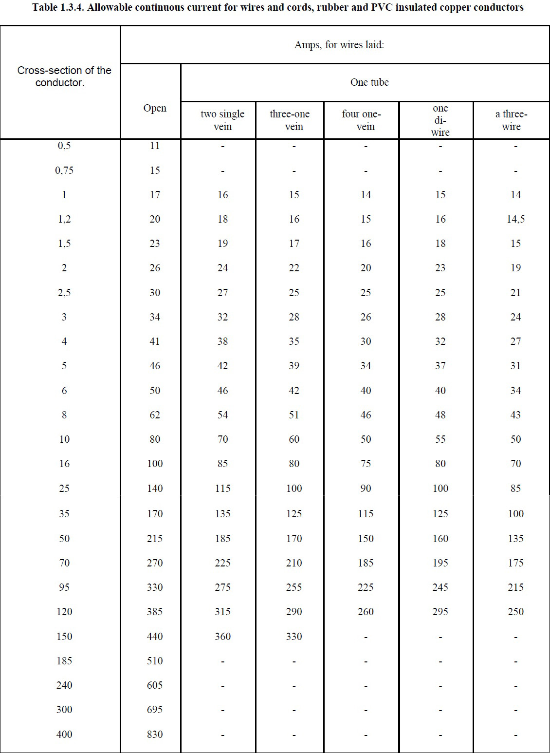
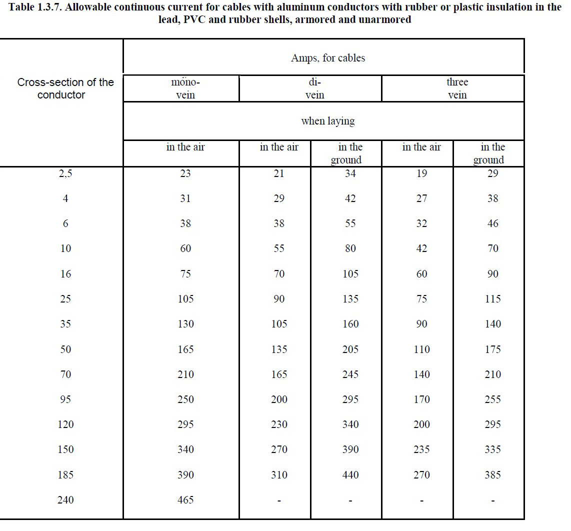
Note. Allowed continuous currents for the four core polymeric insulated cables for voltage up to 1 kV can be selected from Table. 1.3.7, for three-core cables, but with a coefficient of 0.92.
1.3.11. Allowed continuous current for wires laid in the trays, the single-row strip (not in bundles) should be taken as for wires laid in the air.
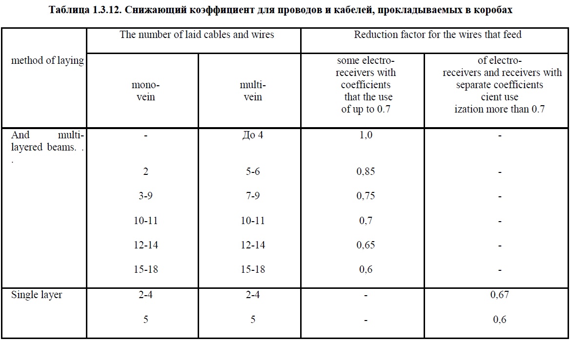
Allowed continuous current for wires and cables installed in ducts, should be taken from Table. 1.3.4-1.3.7 for single wires and cables and openly (in the air) using the reduction factor specified in Table. 1.3.12.
When choosing a reduction factor control and backup wires and cables are not included.
P.S. Die Quelle dieser Informationen: ПУЭ-2009